Rumah> Blog> Automatic tracking of toy car circuit with 555 integrated photoelectric control

Automatic tracking of toy car circuit with 555 integrated photoelectric control

November 04, 2022
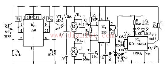
The 555 circuit, which contains two voltage comparators, a basic RS flip-flop, and a discharge switch T, the comparator's reference voltage is provided by a voltage divider consisting of three 5K resistors. They respectively make the non-inverting input of the high-level comparator A1 and the inverting of the low-level comparator A2, and the reference levels of the input terminals are 2/3VCC and 1/3VCC. The outputs of the A2 and A2 control the RS flip-flop state and Discharge tube switch status. When the input signal is from the 6 pin, that is, the high level triggers the input and exceeds the reference level 2/3VCC, the flip-flop resets, the output of the 555 pin 3 outputs a low level, and the discharge switch tube is turned on; when the input signal is from 2 The input of the pin is lower than 1/3VCC, the trigger is reset, the 3 pin of 555 outputs high level, and the discharge switch tube is cut off. RD is the reset terminal (4 pins). When RD=0, 555 outputs a low level. Usually the RD end is open or connected to VCC.

Automatic tracking of toy car circuit with 555 integrated photoelectric control
Photoelectric control automatic tracking toy car circuit diagram


Hubungi Kami

Author:

Mr. Mars SU

Phone/WhatsApp:

+8613728717658

Produk popular
You may also like
Related Categories

E-mel kepada pembekal ini

Subjek:
E-mel:
Mesej:

Your message must be betwwen 20-8000 characters

We will contact you immediately

Fill in more information so that we can get in touch with you faster

Privacy statement: Your privacy is very important to Us. Our company promises not to disclose your personal information to any external company with out your explicit permission.

Menghantar