Privacy statement: Your privacy is very important to Us. Our company promises not to disclose your personal information to any external company with out your explicit permission.
Select Language
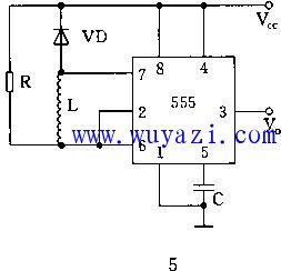
The figure shows a 555 circuit with a multi-vibrator composed of an external resistor R and an inductor L. The oscillation frequency is related to the values of R and L. At the moment of power-on, since the current in the inductor L cannot be abrupt, Il=0, the output of the “1” and 3 pins of the 2 and 6 pins is 0, and the internal discharge tube of the circuit is turned on, and the voltage across the L is approximately equal to the power supply voltage. As Il increases, Vl gradually decreases, that is, the potential of 2 and 6 pins decreases, and when it drops to 1/3 Vcc, the output changes from low to high. At this time, the inner discharge tube of 555 is turned off, and Il is gradually decreased. 2. The potential of the 6-pin is continuously increased with the decrease of Il. When it rises to 2/3Vcc, the output changes from high to low. The oscillation frequency f is proportional to R and inversely proportional to L. In practical applications, R is generally adjusted to change the oscillation frequency.

E-mel kepada pembekal ini

Privacy statement: Your privacy is very important to Us. Our company promises not to disclose your personal information to any external company with out your explicit permission.

Fill in more information so that we can get in touch with you faster
Privacy statement: Your privacy is very important to Us. Our company promises not to disclose your personal information to any external company with out your explicit permission.